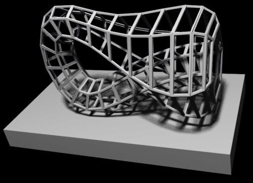
Klein bottle grid object
Click images for larger versions

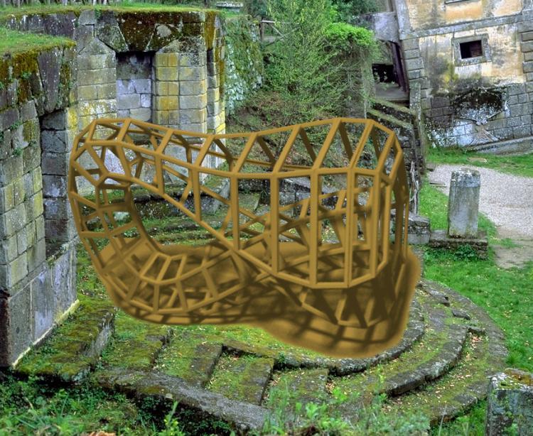
Background photograph courtesy Philip Greenspun
ORIGIN
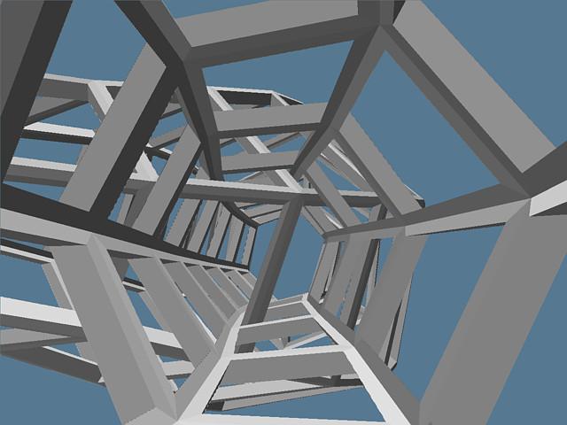
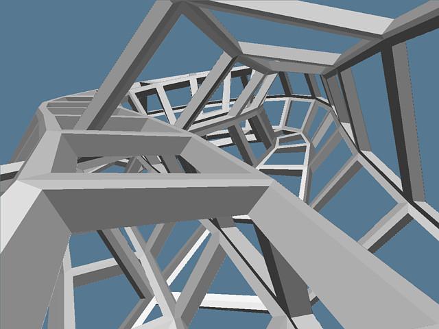
This is a model of the standard immersion of the Klein bottle in three dimensions. The u/v gridlines (in my formulation) are thickened, and special care is taken so that at the circle where the surface self-intersects, the grid does not.
USAGE
A physical model built from this description would make a useful teaching aid. It allows people without access to a computer and 3D viewer to turn a Klein bottle around and examine its features.
In addition, the connectivity of the grid creates a few mobius strips of varying lengths between the grid lines.
FABRICATION HINTS
The complexity of this part demands that it be built using some SFF technique.
The shape is just over two units long, and each grid tube is a near-square .04 units on a side. If the part is sized so the side length is 2mm, the whole shape is just under 4in.
STATISTICS
Cross-section rings: 24
Sides per ring: 6
Object genus: 145
Faces (as triangles): 3456
Vertices (as triangles): 1440
Volume (scaled so side length is 2mm): 11.8 cm^3
Surface area (same scale factor): 25.8 cm^2
PART DESCRIPTION FILES
Geomview OOGL file (quadrilaterals)
VRML file (quadrilaterals)
MUG object (triangles)
STL object
INFORMATION ABOUT THE CREATION OF THIS OBJECT
I wrote an interactive module for Geomview that allows the user to control 12 variables in my klein bottle equations. The program evaluates the u/v equations around the shape and calculates normals, inward points (a small distance into each grid square), and the edge list to describe the gridded shape. It can output to Geomview over a pipe, for instant display, or write SIF.
Here are the parameters to my equations, with descriptions:
-
usteps, vsteps: how many steps to take along u (the long axis) and v (around the cross-section)
-
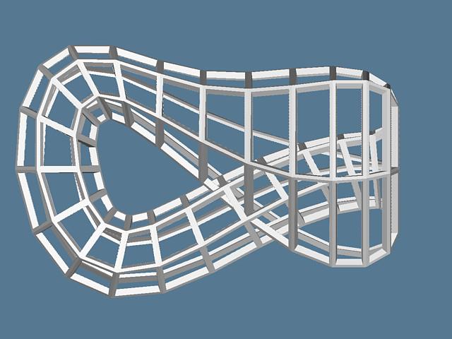
vshift: The gridline that starts at u=0,v=v0 does not connect to itself-- it connects to u=0,v=v0+vshift. This helps prevent gridline collisions at the circle of self-intersection, and it adds a pleasing twist to the grid. This twist is especially visible looking in the "mouth" of the bottle.
-
side,infrac: These are the number of units the grid should be thickened along the normal and along the original surface, respectively.
-
skew: This exponent warps the spine of the bottle in the x-axis so help prevent gridline collisions.
-
perp: This is the coefficient to an adjustment that bends the cross-section such that, at the intersection area, the section with the small radius tilts to become more perpendicular with the section of larger radius.
-
perp start/end angle: These are the starting and ending u values for the adjustment described above. A quartic function is used to make the effect start and stop smoothly.
-
baserad, radamp: The cross-section radius varies from baserad-radamp to baserad+radamp.
-
zpush: This is the coefficient to an expression that pushes the small neck of the bottle out of the plane of symmetry along the same section that is twisted with 'perp'. (zpush=0 in the final shape)
The trickiest part to writing the program was handling the wrap at the end. I tried to write special cases to connect the "outside" to the "inside", etc, to make the grid close correctly. Still, even though I corrected all visible defects, Sara's analyzer told me there were flipped normals and non-manifold edges. Finally, I took advantage of the analyzer's vertex-merging feature: my program does not imagine the bottle to be connected at all, but of course my parameterization returns identical values at u=0 and u=2pi. Removing all the end-connection code and extending the evaluation along u all the way to 2pi created a visually AND geometrically correct part. The analyzer had to fix 2 points where rounding errors outputted slightly different numbers. (View the analyzer's output).
To prevent gridline intersections where the shape self-intersects, I used my interactive geometry generator and the Geomview viewer. Usually, I adjusted Geomview's near and far clipping planes to enclose a very small slice of my shape, so I could see the critical area without any foreground or background geometry in the way. Then I orbited the area over and over so that I could see "sky" between each pair of gridlines that might be intersecting. I never checked the region analytically, but I think I was able to see a gap everywhere there should be one.
See my CS284 project-- it's even prettier!